Targeting Gimbal
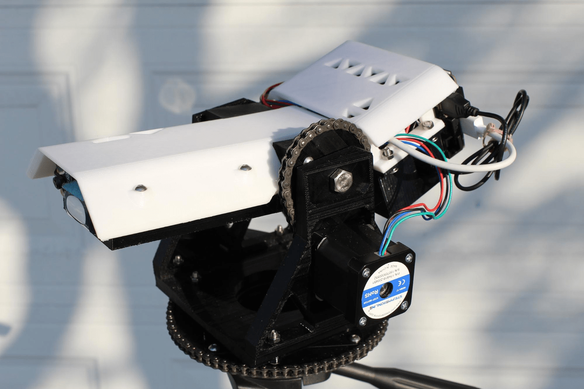
Completed Targeting Gimbal
The targeting gimbal was a high school project, with the goal of being to build a gimbal that can continuously track people. The gimbal was a more complicated project with multiple systems, meaning the main challenge of this project was integrating all the systems. This is currently the only project I have made so far as to include a deep learning neural network, as I wanted the gimbal to be able to target people and objects as well as possible. This project greatly helped me in being able to move to projects with more complex systems as well as designing motor controls and targeting systems.
An initial prototype version was created initially as making one aids me in understanding what specific features are required for the project to work as intended. The first version got many things right, such as the general mechanical design concepts, which transferred over into the final version. The prototype also had an additional tilt axis on top, but I decided to remove that as it would not be utilized that much in general operation. Another difference is that the final version is much larger. The prototype fit all the components snugly which did not consider all the additional things needed such as wires and connectors. I also realized that the smaller gimbal would not be able to meet my requirement of mounting a camera on top.
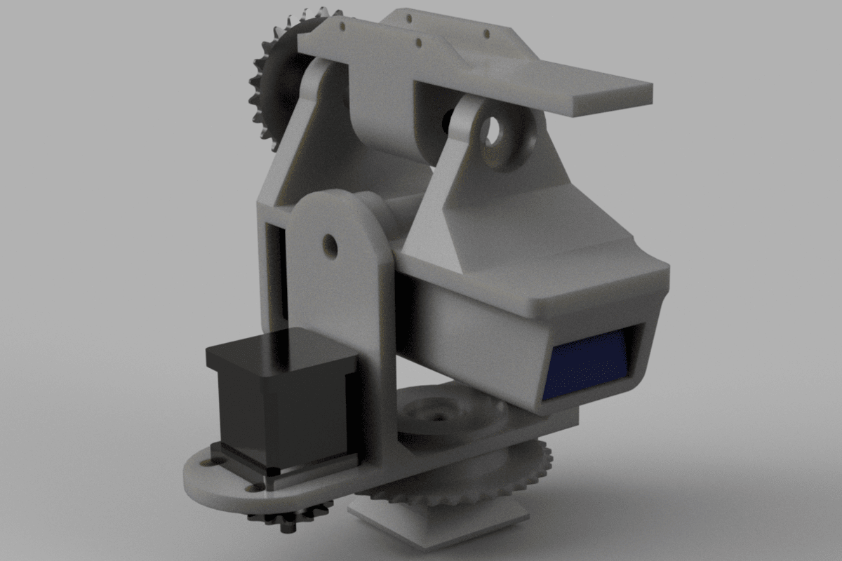
CAD model of the prototype
Mechanical Design
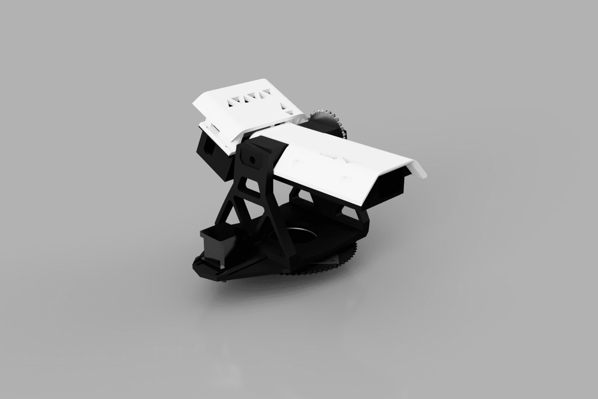
CAD model of final version
The gimbal was designed to be fully 3d printed to facilitate rapid prototyping and ease of manufacturing. The gimbal frame design was optimized for 3d printing, with one of the surfaces of each part being completely flat. The parts were then assembled with screws. The gimbal utilizes a pan and tilt axis, with motion achieved via ANSI 25 chain and 3d printed sprockets which were integrated into the frame parts. Tension was achieved in the chain by the motors mounted in slotted holes. By putting the motor and all the electronic hardware on the gimbal itself, the gimbal has an infinite panning angle.
Since there were many electronic parts in the gimbal, packaging them to create a desired profile was challenging. The electronic breadboards were stacked together in the back, while the Google Coral and battery were laid out flat in the main body. This allowed a lower and slimmer profile of the turret while also having easy access to all the components. The thin main body allowed a large tilt angle without having the mounts be tall.
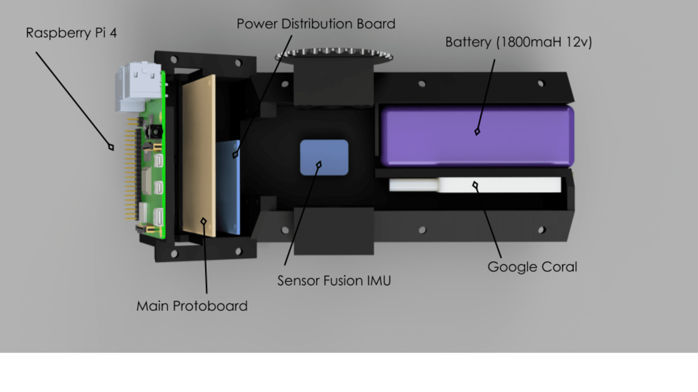
Packaging of the electronic components
Motors and Electronics
I used stepper motors for this project as I was interested in how 3D printers used them. Stepper motors are inherently precise, but not the best choice for this specific application as stepper motors skip when surpassing their rated torque. This can be remedied by using some type of reduction gearbox but was out of my budget at that time. Even then, the stepper motors I chose were enough to handle a large video camera.
One challenge I encountered when trying to develop the motor control code was trying to control two stepper motors simultaneously. The Arduino library I used, however, was blocking, which meant that nothing else could be executed until movement for each stepper was completed. This was insufficient as the stepper motors had to move at the same time to achieve smooth tracking. The solution I came up with was to use two Arduinos connected to each other via I2C, with one Arduino doing the majority of calculations, relaying instructions for the other stepper motor to the other Arduino.
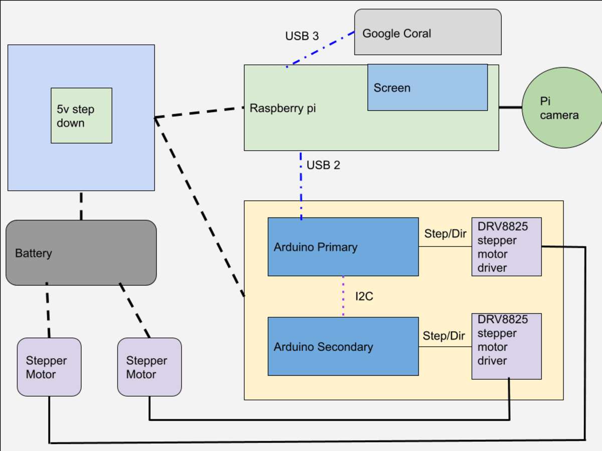
Block diagram of the electronic components
I used the Raspberry Pi with Raspbian OS for the object detection system with the Pi camera. The Raspberry Pi communicated with the main Arduino via USB serial and was powered with a 5V regulator. When I decided to use a Google Coral USB accelerator (explained in the next section) I upgraded from the Pi 3 to Pi 4 as the 4 had USB 3. The targeting was visualized with a capacitive touchscreen kit which seated directly on top of the Pi.
Software and AI
When researching the possible options I had for detecting people, I ended up with two possible solutions, with one using deep learning neural networks, while the other being a algorithmic solution.
The first object detection I tested was to use openCV’s Haar Cascades algorithm in Python. This works by detecting specific patterns in a greyscale image and comparing that to an identifier file. This was easy to implement in Python and worked in Windows and Linux. The main issue with this solution was that it is very resource intensive, with performance on the Raspberry Pi unsatisfactory. I then looked at different solutions involving external coprocessors.
The second method I tried and eventually used was Google Coral. Google Coral is a microprocessor specifically designed to interpret baked AI models using TensorFlow lite. The form factor I specifically used was the USB Accelerator, which was designed to plug into a Single Board Computer, such as the Raspberry Pi. I used a MobileNetV2 object detection model trained on the full COCO dataset. This solution was far more precise and faster, with performance averaging around 120 frames per second, with the Haar Cascades Algorithm being around 20 Frames per second.
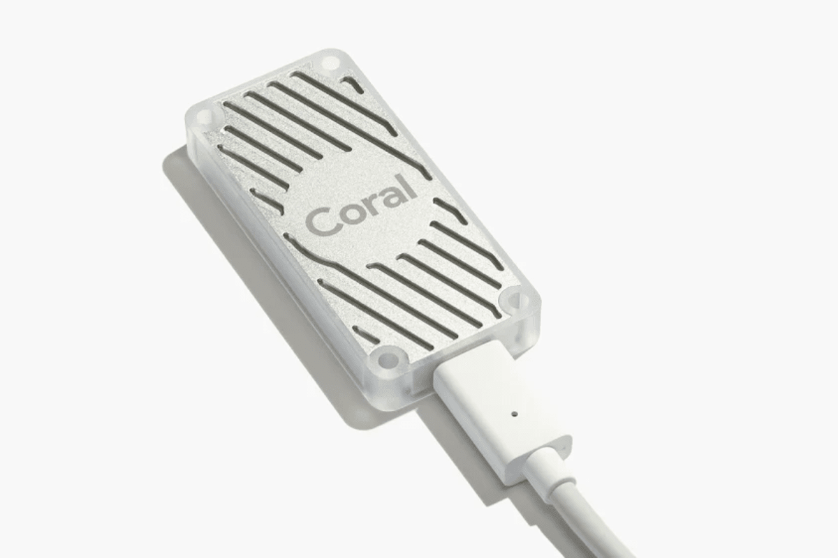
Google Coral USB accelerator
As I have said, the most challenging part of the project was fully integrating the object detection to motor control, which would allow the gimbal to target a person. This was accomplished by drawing a target circle in the Python detection program and drawing a dot on the target. Depending on where the target is in relation to the target circle, the detection program would send the pixel difference to the Arduino. The Arduino then decides at what direction and speed to move each of the stepper motors.