Electric Scooters
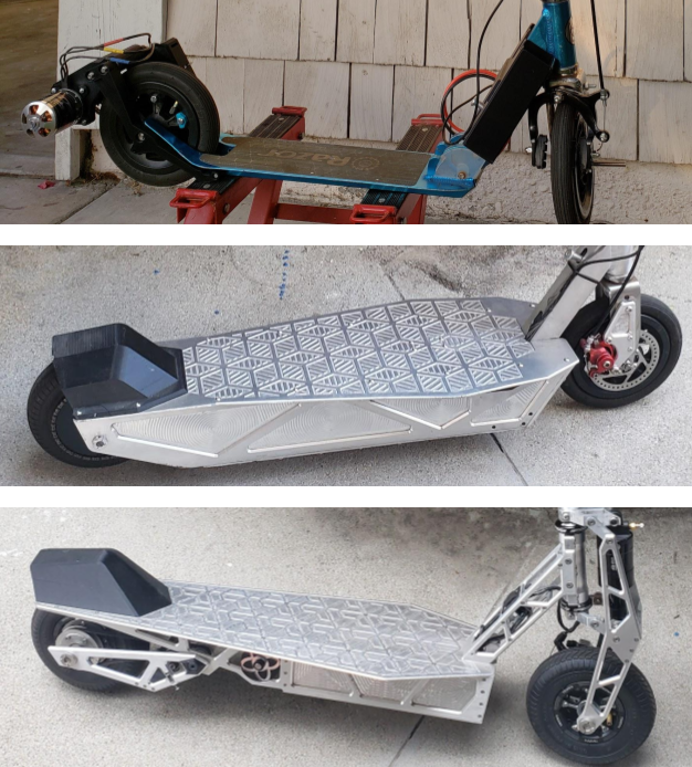
(top to bottom) Mark I, II, and III electric scooters
The goal of this project was to create my ultimate electric scooter. It spans three iterations with each version greatly different than the last. This project’s rigorous requirements challenged all of my skills. This report is split into the different subsections of the scooter with details about each version.
The electric scooter project was one of my longest projects, with the first version built in 2019. The project initially began as a high school physics project, which meant I did not have much to work with. The structure was mainly 3d printed, right down to the chain sprockets. The scooter was not very robust and served better as a demonstration. To make a serious electric scooter, a stronger material was needed, such as aluminum.
Allowing this change was the acquisition of a Shapeoko 3 router CNC, which would allow me to create precise aluminum parts. This led to the MKII, which retained the same power system and front fork as the MKI, but with a machined main chassis. The MKII was finished in the summer of 2020, with development taking about 6 months. This was a success, as the scooter was powerful and reliable, after a few teething issues. But I still sought more performance and was not fully satisfied, which led to the MKIII.
The MKIII is as close to my perfect scooter as I can get, using all the lessons and skills I have learned building the first two. It features a fully bespoke aluminum frame, with front and rear suspension. Combining this with a powerful motor with a belt transmission results in a very smooth ride with immense power. Because of the greatly increased complexity of the scooter and college responsibilities, development took around two years with multiple iterations to each subsystem. I could call the scooter in a finished and usable state in the fall of 2022, but development doesn’t ever end, does it?
Specifications
| MK.1 | MK.2 | Mk.3 | |
|---|---|---|---|
| Motor | 3.5 kW brushless outrunner | 3.5 kW brushless outrunner | 4.4. kW sensored outrunner |
| Battery | 5s 4200 mAh x2, series | 10s 3p individual 18650 cell design, bolted construction | 12s 3p individual 21700 cell design, spot welded |
| Drivetrain | Plastic sprockets, ANSI 25 chain | Steel and aluminum sprockets, ANSI 25 chain | 2X gates GT3 5m belts, aluminum pulleys |
| Wheels | Solid Urethane 200x25 | Front:200x25 pneumatic Rear:200x50 pneumatic | Both 200x50 pneumatic |
| Max range | Untested | 5 mi | 10 mi |
Structure
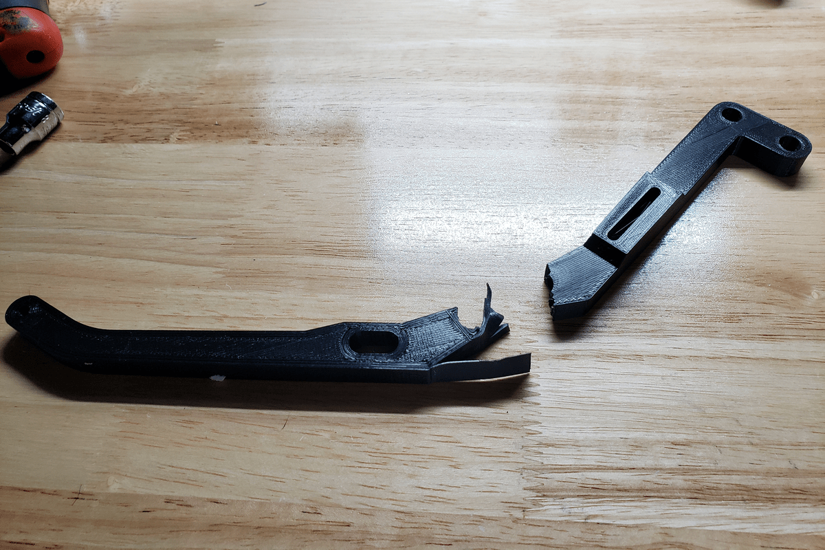
Testing the tensile strength on the main arms
When first starting out on this project, I did not have many resources as this was primarily a high school project to be done in two months. I did have a 3d printer, and I decided to make all the parts using the 3d printer as it was very fast and easy. The MKI at its roots is two plastic arms that attached to the motor on top of the wheel. I tried multiple ways to couple the motor to the wheel, as it was difficult due to working with the small razor scooter frame. I first tried using a smaller urethane drive wheel that spun the wheel by friction, but soon switched to using ANSI 25 sprockets, which was also 3D printed.
I needed to maximize the strength of the arms, so I experimented with multiple plastics, including PLA, PETG, and PC. I found that even though polycarbonate was stronger, it bent more than PLA, which made it unsuitable for this project. I then attempted to make aluminum arms with hand tools, but ultimately acquired the Shapeoko 3 CNC router.
The router CNC, equipped with a tungsten carbide end mill, was perfectly capable of machining aluminum alloys, which allowed me to greatly increase the scope of this project. The second and third scooters mainly used large ¼ and 1/8 plates, which plays to the strengths of the CNC router.
The MKII had a machined deck assembly, which allowed a bigger battery to fit in. I was still growing accustomed to machining, so the CNC parts were simple. I used my experience with the MKII to construct the MKIII, which was much more involved.
The MKIII features a fully bespoke frame and front and rear suspension. This necessitated much more ambitions CNC toolpaths which required multiple surfaces to be machined. The complicated parts such as the front suspension knuckles and the fork mount were machined out a 2 inch thick aluminum bar. In total, 30 parts had to be machined. to minimize weight, finite element analysis was used to determine an optimum shape. Because the whole frame was designed, I could control factors such as wheel base and rake angle, where I increased the rake for stability.
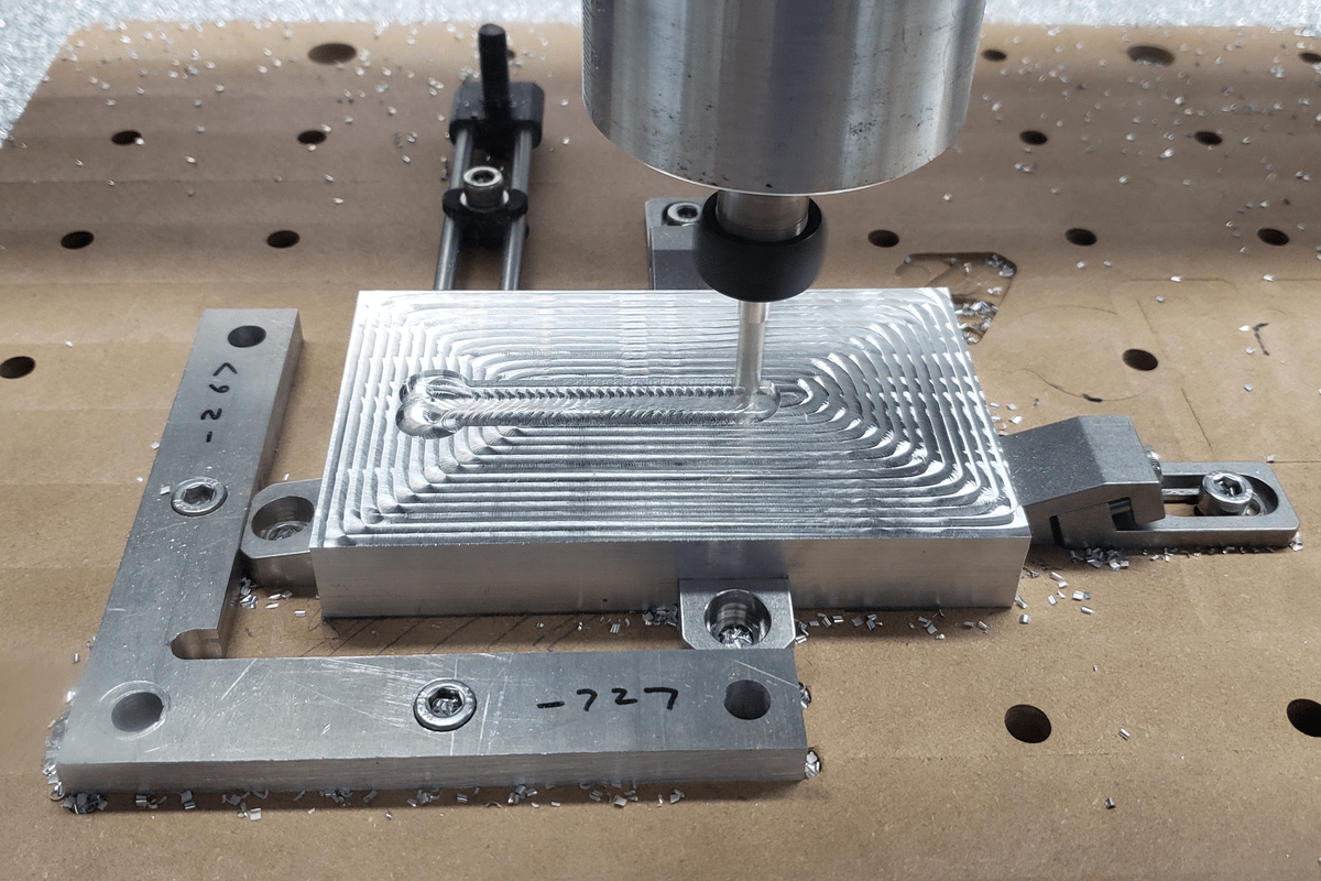
MK.3 head tube being cnc machined
The pneumatic suspension of the MKIII ensures stability at high speeds, which was an issue with the MKII. Pneumatic suspension was specifically chosen to allow greater adjustment and control over behavior. The front shock has 41mm of travel and the rear shock has 20mm of travel. I had to carefully design the linkage geometry so that the front and rear wheels have the same amount of travel. Because of the limited space in the front, the linkage is like a double wishbone suspension, while the rear is a simple trailing arm. All the joints use shoulder screws with oil impregnated bushings. The limited space in the rear to fit a shock created an interesting packing problem for the belt powertrain, which is discussed in the next section.
Powertrain
The MKI used two 5s li-po packs in serial to create a 30V battery pack, with a capacity of around 4 Ah. When creating the MKII, I knew I needed a much larger battery. The first custom battery I made used 18650 li-ion battery cells in a 10s3p configuration, which gave a capacity of around 12.5 Ah. Without a battery spot welder, I used a kit where the tabs were secured with nuts. This was easy, but meant the battery is not very space efficient. When designing the second battery for the MKIII, I got a proper battery spot welder, and 3d printed a cell frame that more efficiently packs the larger 21700 cells together in a 12s3p configuration, with 13.5 Ah capacity. The result of this is a battery smaller than the first one with more voltage and capacity. Both of the built batteries use a battery management system that balances each series section and adds over voltage and temperature protection.
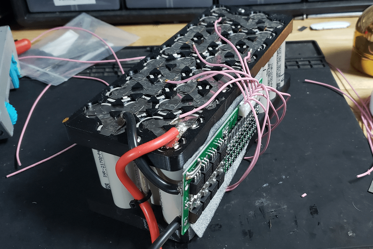
MK.3 battery partially assembled
When choosing a way to transfer the motor torque to the wheels, ANSI 25 chain was selected due to the space restricted design of the MKI. The 3d printed sprockets of the MKI were not very durable, so the MKII had steel sprockets from Misumi. Because of the high wheel rpm, the chain was very noisy, and without an idler, would frequently fall off of the sprocket.
When designing the MKIII, I wanted a much higher wheel reduction in order to have much more torque. The MKIII utilizes two Gates Powergrip GT3 belts, with four sprockets from Misumi. To deal with the trailing arm suspension, the two belts meet at a midaxle placed at the rotation point, allowing the belt to stay in constant tension with two idler pulleys. Earlier designs had an axle through the linkage joint and the pulleys but proved insufficient to handle the thrust loads of the rear wheel.
The first two scooters shared the same 3.5kw outrunner motor. Due to the motor being designed for large scale RC planes, it did not have a sensor and had low torque at low speeds. The MKIII motor has more power and has a speed sensor, as it was specially designed for e vehicles. An issue is that the motor outputs 400w of waste heat at full power, which it cannot dissipate due to the sealed design. To remedy this, I machined a water block which attached to a radiator mounted on the scooter.
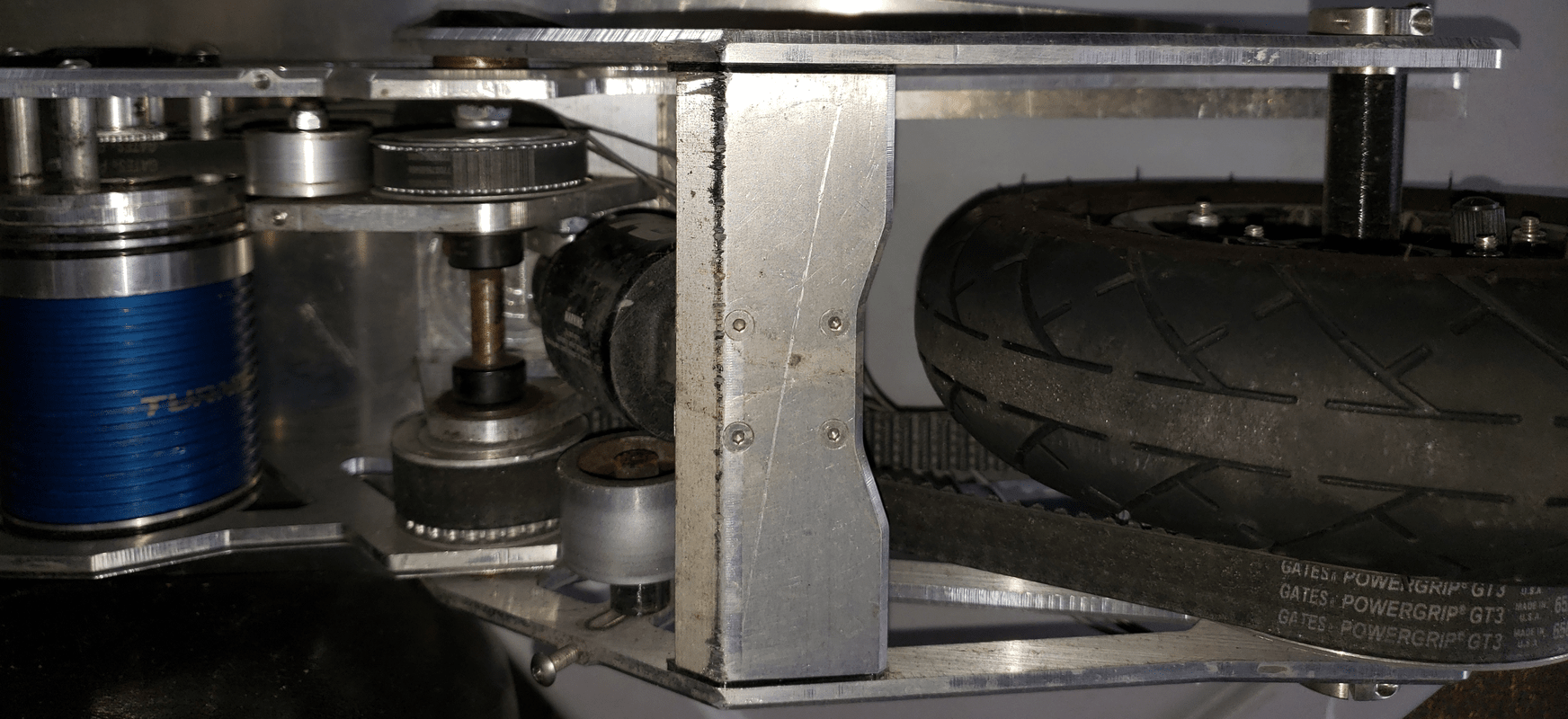
MK.3 dual belt powertrain
Electronics
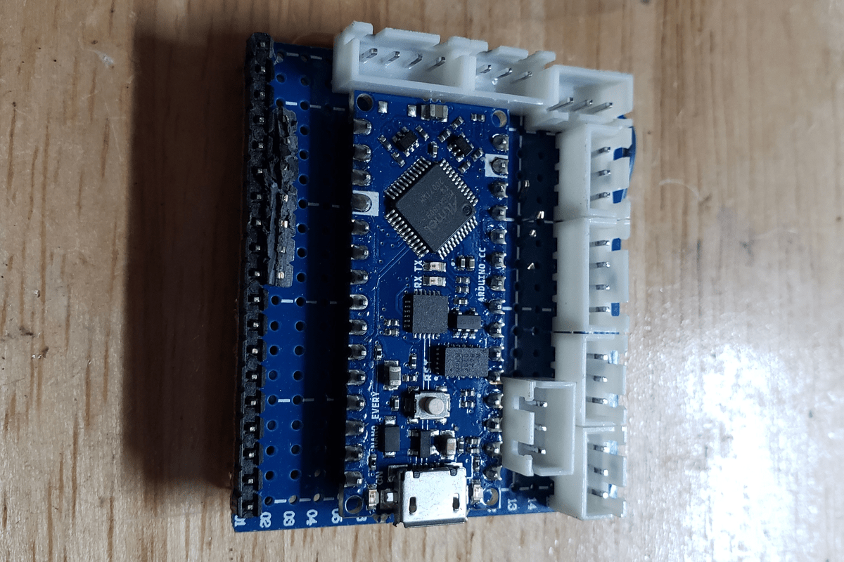
prototype MK.3 perfboard
At the end of developing the MKII, I decided to put a speedometer screen to show speed, charge, voltage. To obtain data, I used an Arduino which interfaced with the speed controller, via serial. Because of the low power budget, an oled screen was chosen. Even though it was fast, the screen was not very bright in sunlight. For the MKIII, a full color tft was used which was much brighter and larger. Additionally, more algorithms were coded into the MKIII to allow an odometer, miles range, and efficiency. The circuits were packaged using perfboards, which allowed more durability and compactness than breadboards.
Lighting was by far the most complicated system on the MKIII. Due to the higher power requirements, a separate high current 5v voltage rail was needed. The MKIII features a headlight, handlebar indicators, rear taillight and rear flasher. The headlight is a deconstructed bike light with a transistor attached to the button signal, allowing Arduino control. For the taillights, a separate Arduino was needed to allow proper serial communication. The system is controlled via a thumbstick attached to the handlebar.
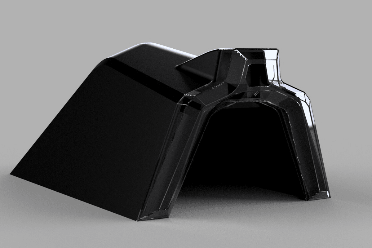
MK.3 rear tailight design
Design Language
Throughout building each of these scooters, especially the MKII and III, I wanted to make the design as aesthetically pleasing to me as possible. This is a challenge due to how the scooters are constructed. Each part needs to be strong and structurally sound, while also meshing well with the design. I had to make concessions at places, of course, but in the end, I feel like I struck a nice balance. If you look very closely, you can see that the scooters have a base geometric shape. I wanted to keep the aluminum brushed finished, to create a sharp or raw look. To pursue cleaner lines, primarily countersunk screws were used in the MKIII. The centerpiece of the scooter is the baseplate/deck. In order to keep the aluminum finish, the deck has very small, machined steps around each part to ensure good grip.