Multirotors
Bicopter (early version)
Building a quadcopter was one of the first larger projects I undertook. I built a quadcopter with minimal prior knowledge, which as a result took two tries. The bicopter was a much later project, and I had to adapt to new multirotor technologies and systems that had advanced greatly since I last built the quadcopter.
The Building Experience & Lessons Learned
The quadcopter project began around 2014, when I was in middle school. Before this, I haven’t done a project at this scale before, only tinkering with Arduino kits and disassembling everything I could. I played a lot with small remote controlled helicopters, so I decided to make my own quadcopter. I had no previous experience or knowledge on building a quadcopter and what it takes so I tried to find a guide to build one. I did find plenty of guides, but the guides, while containing helpful information, did not tell me exactly what to do for my specific set of parts. A quadcopter is highly customizable with no straightforward way of how it is put together. I had to learn why each guide did what they did in order to apply it to my own quadcopter. This greatly helped in fostering the skill of problem solving and the general mindset that each choice in a design has a purpose. Learning this enabled me to move on to my later projects, which had no guide at all.
Quadcopter
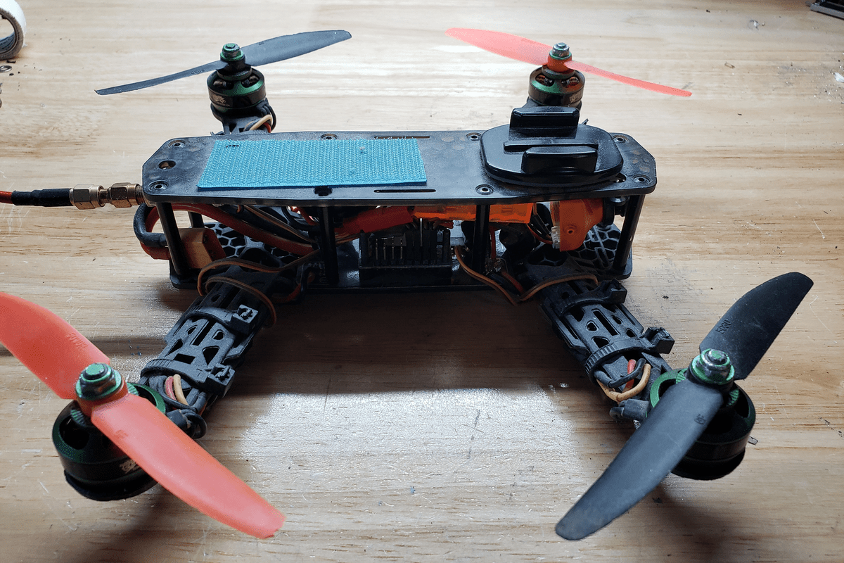
The second attempt at making a quadcopter
When first starting out on this project, I did not have many resources as this was primarily a high school project to be done in two months. I did have a 3d printer, and I decided to make all the parts using the 3d printer as it was very fast and easy. The MKI at its roots is two plastic arms that attached to the motor on top of the wheel. I tried multiple ways to couple the motor to the wheel, as it was difficult due to working with the small razor scooter frame. I first tried using a smaller urethane drive wheel that spun the wheel by friction, but soon switched to using ANSI 25 sprockets, which was also 3D printed.
I needed to maximize the strength of the arms, so I experimented with multiple plastics, including PLA, PETG, and PC. I found that even though polycarbonate was stronger, it bent more than PLA, which made it unsuitable for this project. I then attempted to make aluminum arms with hand tools, but ultimately acquired the Shapeoko 3 CNC router.
The reason I chose to build a quadcopter was because I was enamored with the idea of first person view, or flying the drone using a live camera feed from the drone. During this time this was accomplished with a 5.8ghz analog signal. There were many factors to get a good transmission, such as choosing a correct channel, transmission power, and video connection with the small CCD designed camera I viewed the video through cost effective FPV goggles, which were essentially a Styrofoam box with a screen at one end and a Fresnel lens on the other. It worked, as video quality was not that important. Achieving a robust signal from the drone was difficult, as I tried multiple video transmitters and receivers. I could never get a range longer than about 10 meters. I was using low power transmitters and possible interference was high, as wifi routers operate in that range. Nevertheless, I was content with the result.
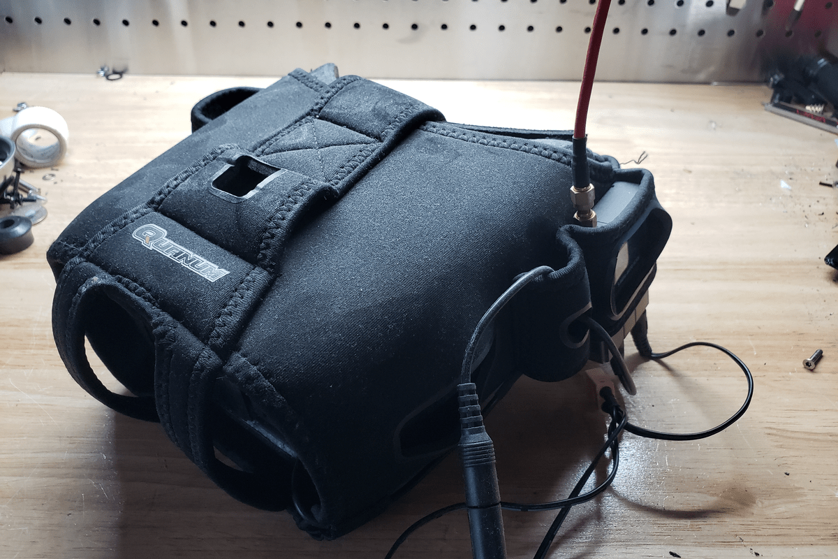
The cost effective FPV goggles I had
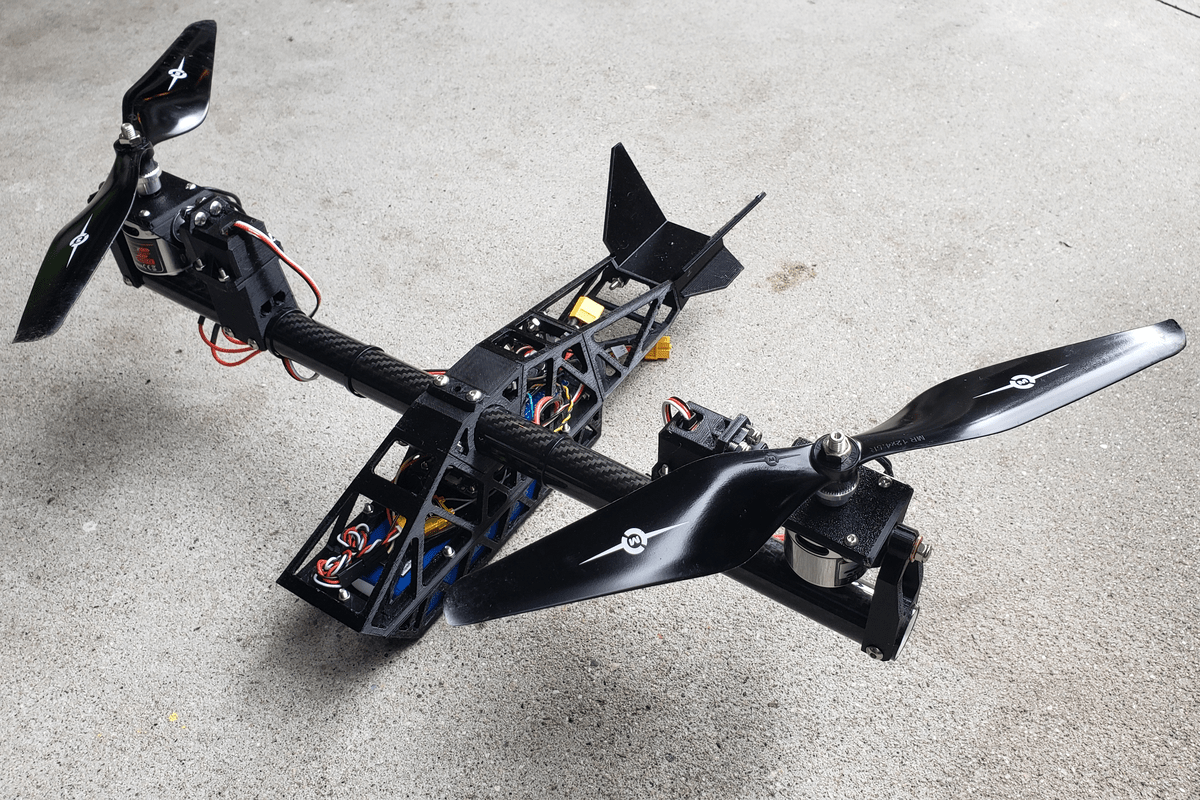
Bicopter
The bicopter was a separate project from the quadcopter and made years later for a high school project. I wanted to get back into making drones, but I did not want to make a second quadcopter. I decided on the least popular form of the multirotor: the bicopter. Even though I already knew what was needed for flight, I had to relearn the new technologies that were created for drones. In essence, a bicopter has two rotors attached to two servos on a main beam. Movement is achieved by having different rotor speeds and tilting the motors which were affixed on a rotating beam powered via sevo. The result is something that resembles the Boeing V22 Osprey. The bicopter did not have a FPV system, as it was out of the scope of this experimental project.
later model of the bicopter with gopro attached
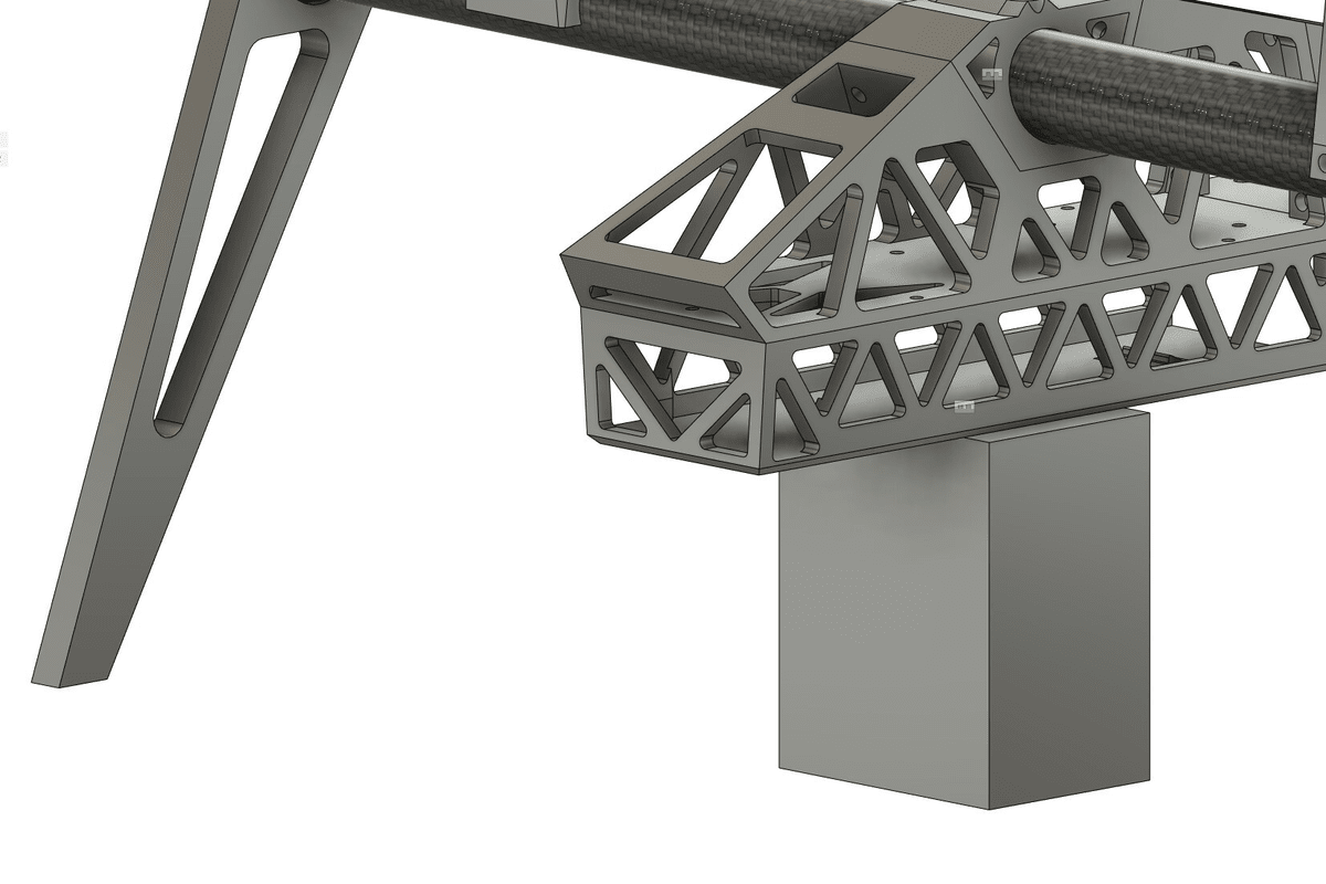
The bicopter features a fully 3d printed frame that attaches to a round carbon fiber pipe, which connects to the two servo tilt assemblies. The frame was split into two parts to allow for easier 3d printing, with the bottom part holding the battery. I chose PETG for the printing material as it was UV stable and impact resistant compared to PLA. To attach the frame to the tube, I also printed inserts that go inside the tube that holds a nut, with the bolt screwed in from the outside. The design heavily uses a triangle trellis pattern in the hopes of getting it as light as possible.
The flight controller was placed as close to the center of the multirotor as possible, with servo power and motor power off to the side. The flight controller was configured via connecting it to a pc and using a program, which was very helpful when trying to set up the bicopter. The bicopter configuration was supported, but it was a challenge to connect and use the servos. Due to the large size of this multirotor, the PID values for movement were set very low, as any higher would cause oscillations of the servo.
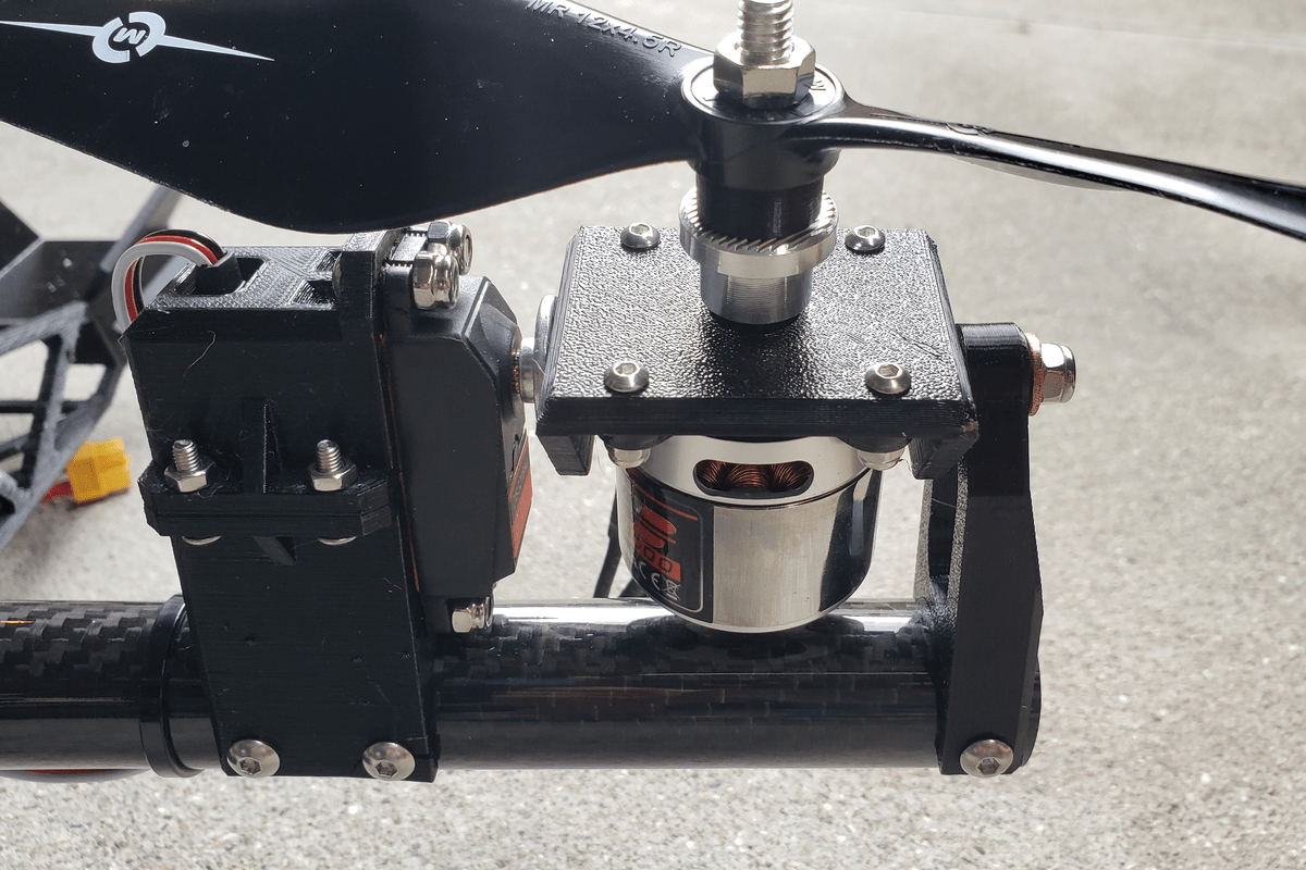
The bicopter servo tilt mechanism
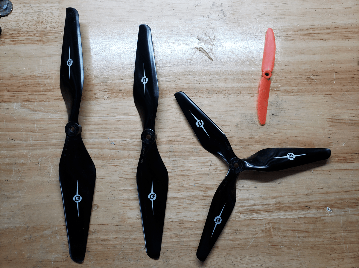
comparsion of the 12, 11, 9 inch bicopter propellers, with a 5 inch quadcopter propeller for comparsion
I designed the layout of the parts in the frame to be compact and narrow to achieve a sleek look. However, this meant that the center of gravity was closer to the motors, which does not help in stability. The bicopter would start oscillating and would ultimately crash. The oscillations were caused by the servos not being able to move fast enough or precisely enough to stabilize the multirotor. In an attempt to remedy this without redesigning the frame, I attached a gopro camera to the bottom, which was moderately successful. I also played around with the propeller size, switching between 12,11, and 9 inch diameters (the 9 inch propeller had three blades). The 11 inch propellers were the most stable. When designing future bicopters, I will try to achieve a more vertical design to create a larger moment of Inertia. Additionally, a smaller bicopter with a faster servo assembly would be able to balance much better.